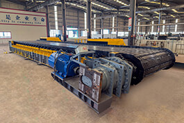
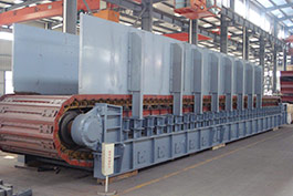
Compared with frequency conversion technology, the research of hydraulic drive technology started early, and the research is more thorough. The starting and accelerating impact of the hydraulic drive mode is small, the flexibility is good, and the system always runs in a relatively stable state. As an important part of the semi-continuous system of Yimin open-pit mine, the self-moving crusher was introduced from Germany in 2007. The coal feeding system of the crusher is
apron feeder, the driving mode is hydraulic drive, the rated working speed is 0.5ms, the maximum working speed is 0.6ms.
1. Working principle of hydraulic system
The apron feeder driving part uses variable pumps-quantitative motor, which is a volumetric speed regulation and closed hydraulic system. Volumetric speed regulation by changing the displacement of the hydraulic pump to adjust the speed of the actuator of the hydraulic motor, because there is no throttling loss and overflow loss, high loop efficiency, small system temperature rise, suitable for high-speed, high-power speed regulation system.
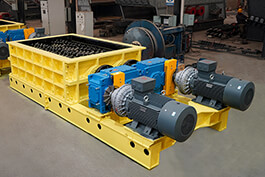
1.1 Drive Unit
The
apron feeder drive unit consists of two vertical motors and a growth gear box, which is equipped with a cooling device. When the system is running, the gear oil circulates between the gearbox and the radiator. The gear oil circulation pipeline is provided with a pressure sensor to ensure sufficient oil in the gear box. According to the design requirements, the pressure should not be less than 0.2MPa.
The hydraulic system is more complex, hydraulic as the name suggests is liquid as the working medium for power transmission, by the relevant hydraulic components control, the final output power to the processing equipment for a series of actions. Hydraulic components generally include power components, control components, executive components, auxiliary components and so on. Hydraulic transmission is the use of hydraulic pump to transform the mechanical energy into the pressure energy of the liquid, and then use the hydraulic cylinder to transform the pressure energy of the liquid into the mechanical energy to drive the load, and each actuator to complete the required movement speed. Hydraulic transmission has greater advantages than mechanical transmission and pneumatic transmission:
① Can achieve stepless speed regulation, speed regulation range, up to 100:1~2000:1.
② can transmit large force and torque. Small size and light weight compared with mechanical devices.
③ Stable work, small impact: simple control and adjustment. Remote control can be achieved with electrical cooperation.
④ Long service life, self-lubricating. The heat produced is carried away with the flow of the liquid. The working medium of hydraulic transmission is mainly hydraulic oil. The reasonable selection of hydraulic oil has great influence on the working state of hydraulic system. The main properties of hydraulic oil are viscosity and compressibility.
The main
apron feeder factors affecting viscosity are temperature and pressure. When the pressure increases, the viscosity also increases, and the change of viscosity can be ignored under medium and low pressure. As the temperature increases, the viscosity decreases. Generally, hydraulic oil with large viscosity should be selected at high temperature to reduce leakage, and hydraulic oil with small viscosity should be selected at low temperature to reduce friction. The selection of hydraulic oil should be determined according to the requirements of the hydraulic pump. L-HM32#/46#/68# hydraulic oil is recommended when the working pressure of the vane pump is less than 7MPa, and L-HM46#/68#/100# is used when the working pressure is greater than 7MPa. L-HL32#/46#/68# hydraulic oil is recommended when the working pressure of the gear pump is less than 12MPa; When greater than 12MPa, L-HM46#/68#/100#/150# hydraulic oil is used. The recommended oil for the piston pump is L-HM32#/46#/68#/100#/150# hydraulic oil. Screw pump oil recommended L-HL32#/46#/68#. The hydraulic cylinder is the actuator of the hydraulic system, which realizes the reciprocating movement in a straight line or less than 360°. The hydraulic cylinder is divided into piston type, plunger type and swing type according to the structural characteristics. The hydraulic control valve is a control element in the hydraulic system, which is used to control the pressure, flow and flow direction in the hydraulic system. It is an important element that directly affects the working process and working characteristics of the hydraulic system. Hydraulic valves are divided into pressure control valves, flow control valves and direction control valves according to their use. The basic structure of the hydraulic valve mainly includes a valve spool, a valve body, and a control device that drives the valve spool for relative movement in the valve body. The working principle of the hydraulic valve is to use the relative movement of the valve core in the valve body to control the opening and opening size to achieve the control of pressure, flow and direction. Hydraulic electric motor pressure control valve includes relief valve, pressure reducing valve, unloading valve, pressure relay, etc. Flow control valve includes throttle valve, speed regulating valve, etc. Direction control valves include check valves, reversing valves, stroke reduction valves, etc. There are ordinary check valves and liquid-controlled check valves, which only allow liquid to pass in one direction, while the reverse flow of liquid is cut off. The check valve is generally installed at the outlet of the pump, which can prevent the pressure impact of the system and prevent the oil flow back through the pump to the tank, and also prevent oil circuit interference.
.jpg)