Address: Middle of Xinchang North Line, Xinxiang City, Henan Province, China
Time:Aug 28th, 2023
Pageviews:
Share:
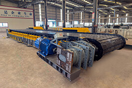
Apron Feeder Lockplate Working Principle And Installation Steps
A) Apron feeder locking disc principle
The locking disc of the reducer is a hollow shaft, and the locking area is matched with the apron feeder head driving shaft. With the bolts tightening the locking area, the inner diameter of the cone sleeve is continuously reduced, and the solid shaft is held and the torque is transmitted by static friction force. Do not apply any lubricant to the locked area. The locking area on the hollow shaft should not have any grooves.
The principle of the locking disc;
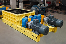
In the connection between the wheel and the shaft, the locking disc is a keyless connection device that realizes the load transfer by tightening the pressure and friction generated between the inclusive surface by tightening the high-strength bolt, so as to realize the connection between the planetary reducer and the apron feeder drive shaft to transfer the load. When used through the role of high-strength bolts, so that between the inner ring and the shaft, between the outer ring and the hub produce a huge holding force, when bearing the load, by the expansion sleeve and the combined pressure and friction generated by the associated torque transfer, axial force or the composite load of the two.
If the stiffness is similar, alternately tighten evenly. The screws are tightened in order to prevent uneven fastening of the bolt or screw connection from causing skew and failing to meet the requirements of the pre-tightening force. Select tightening sequence locking disc according to stiffness requirements.
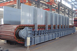
The locking disc is used to connect the reducer to the drive shaft of the plate feeder. The processing requirements of the locking disc hole are high, the structure is simple, the installation and disassembly are convenient, and the application is wide.
2) Apron feeder lock plate installation steps:
1. The operator should be familiar with the installation parameters before installation, and check the installation size of the shaft and shaft sleeve, and confirm that it can be installed when it meets the standard.
2. wipe the anti-corrosion oil of the locking disc, and apply lubricating oil with molybdenum disulfide lubricant on the conical working face and screws).
3. wipe the shaft and shaft sleeve hole, degreasing treatment.
4. Install the locking disc on the shaft sleeve, and take any three locking screws to form an equilateral triangle. Tighten the screw gently until the inner ring can still turn the lock disc on the shaft sleeve.
5. Load the shaft into the shaft sleeve and let the shaft sleeve rotate on the shaft.
6. Use the torque plate hand to tighten the locking disc screw. The tightening method is to tighten the screw successively according to the equilateral triangle order, screw it to 1/4 of the tightening torque MA value, and then increase the 1/4 tightening torque value successively to tighten it.
7. Tighten the screw repeatedly according to the tightening torque MA value (N.m) to ensure that each locking screw reaches the tightening torque value.
3) Apron feeder locking disc disassembly sequence:
1. Gradually loosen all the locking screws, each cycle loosen 1/4 turn. When the outer ring can not be removed, use the disassembly screw hole to screw in the corresponding screw to loosen the outer ring.
2. If rust occurs in the shaft head before the shaft sleeve, rust must be removed before disassembly.
3, The removed lock disc is still reinstalled in the installation order, and pay attention to the relative position of the two outer rings and the inner ring to prevent reversal. If the O-ring is damaged, it should be renewed.
.jpg)