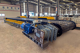
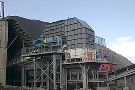
Apron feeder is mainly used to transport all kinds of bulk or loose materials from storage to crusher, conveyor or other working machinery in a horizontal or inclined direction. Widely used in building materials, gold, mining and other industries, is an indispensable equipment in raw material treatment or continuous production process.
We designed an apron feeder, which includes a motor, head shaft assembly and head sprocket, tail shaft assembly and tail sprocket, frame and a bracket welded on the frame, the bracket is fixed with a guide plate and a trough plate, and the trough plate is connected with a traction component and a bearing component, the bottom of the trough plate is provided with a wear-resistant plate, the upper central rack is provided with a heavy rail, and the traction component is a traction chain. In view of the above related technologies, we believe that when the material falls from the top and impacts the trough plate, the trough plate will drive the traction chain to move downward, and when the material stops falling, the traction chain will rebound. When the apron feeder runs for too long, the traction chain will be loose, resulting in unstable materials transported by the trough plate.
.jpg)
In order to ensure the stable operation of the transport tank, an apron feeder that can reduce chain wear is provided. An
apron feeder that can reduce chain wear uses the following technical solution: an apron feeder for reducing chain wear comprises a frame, a chain plate mechanism arranged on the frame, a first drive mechanism for driving the rotation of the chain plate mechanism, the chain plate mechanism comprises a track chain and a transport trough, and also includes a tensioning mechanism for controlling the tension of the track chain, and an automatic regulating mechanism arranged on the frame. The tensioning mechanism comprises a guide wheel engaged with the track chain arranged on the frame and a driving component driving the guide wheel to move, the automatic adjustment mechanism comprises a tensioning wheel arranged on the frame and matched with the track chain, and a third spring fixed on the frame for driving the tensioning wheel to move. By using the above technical solution, when the track chain is loose, the tensioning wheel moves under the action of spring elasticity, and the tensioning wheel keeps the track chain in a tensioning state. However, there is a certain limit for the tensioning wheel to adjust the tightness of the track chain. When the limit is exceeded, the operator can start the pushing component to make the guide wheel move. The guide wheel makes the track chain maintain the tensioning state, and makes the tensioning wheel restore the initial state, and the track chain maintain the normal state, which is conducive to the smooth operation of the transport trough. The driving assembly comprises a fixed sleeve fixed on the frame, a rotating nut installed on the opening end of the fixed sleeve, a screw rod threaded through the rotating nut, one end of the screw rod is arranged in the fixed sleeve and is slip-matched with the fixed sleeve, the other end of the screw rod is connected with the guide wheel, and the rotating nut is connected with the screw screw thread.
The operator pulls the nut by rotating the apron feeder bolt, making the lead screw move from the fixed sleeve to the guide wheel, and the lead screw pushes the guide wheel against the track chain. The rotating assembly comprises a second motor arranged on the frame, a driving gear fixed on the output shaft of the second motor, a driven gear engaged with the driving gear, a worm fixed on the driven gear, a worm wheel nested on the rotating nut and threaded with the worm. The worm wheel is fixedly connected with the rotating nut. The second motor starts, the output shaft of the motor rotates to make the driving gear rotate, the driving gear rotates to drive the driven gear, the driven gear rotates to make the worm rotate, the screw rotates to make the worm wheel rotate, and the worm wheel drives the rotating nut to rotate. The use of worm wheel and worm prevents the apron feeder's track chain from forcing the guide wheel to move. A mounting mechanism is arranged on the frame, and the guide wheel is detachable connected with the mounting mechanism, and the lead rod is detachable connected with the fixed sleeve. When the guide wheel wear is serious, the operator can remove the guide wheel for replacement. The inner wall of the fixed sleeve is provided with a chute, and the length direction of the
apron feeder chute is the same as the length direction of the fixed sleeve, and the slide block is fixed on the lead rod, and the chute is slithered with the slide block. By adopting the above technical scheme, the slide block and the lead screw are fixed connected, and the slide block can only slide along the direction of the chute, so that the lead screw cannot rotate in the fixed sleeve, and the sliding coordination between the slide block and the chute makes the lead screw move more smoothly.