Address: Middle of Xinchang North Line, Xinxiang City, Henan Province, China
Time:Oct 11th, 2023
Pageviews:
Share:
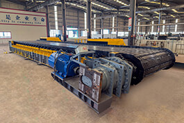
Large Heavy Duty Apron Feeder Composition And Design Process
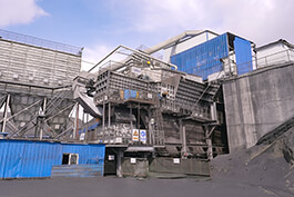
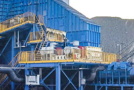
Apron feeder is generally divided into heavy, medium and light three kinds, is commonly used in the concentrator feeding equipment, heavy apron feeder is the auxiliary equipment of transportation machinery, the machine in the large concentrator crushing and grading workshop and cement, building materials and other departments, as a silo to the primary crusher continuous and uniform feeding. It can also be used for short distance conveying materials with large particle size and specific gravity. It can be installed horizontally or tilted, with a maximum inclination of 12 degrees. In order to avoid direct impact of materials on the feeder, the silo is required not to be unloaded. However, the currently used large-volume heavy-duty apron feeder, the material transported will be stuck on the conveyor chain, and even fall directly to the bottom of the feeder, which will cause damage to the feeder jam over time and reduce the feeding speed.
We designed and produced a large-volume heavy-duty apron feeder, which can effectively solve the current large-volume heavy-duty apron feeder proposed in the above background technology. The material transported by it will get stuck on the conveyor chain, and even fall directly to the bottom of the feeder, which will cause the feeder plug damage and feed speed reduction over time. We provide the following technical solutions: A large-volume heavy apron feeder comprises a frame, the bottom of the frame is symmetrically installed with a connecting plate, the inside of one connecting plate is provided with a clamping slot, the other connecting plate is provided with a clamping hole through the inside, the clamping shaft is connected between the clamping slot and the clamping hole, both ends of the mounting shaft are installed with a clamping block. One end of the mounting shaft corresponds to the clamping hole position where the screw is connected with a fixing nut, the middle of the mounting shaft is embedded with a support plate, the middle thread of the mounting shaft is connected with a fixing bolt, and the top of the supporting plate is fixed with a cleaning head: The bottom end of the connecting plate is installed with a bottom plate, the top of the bottom plate is installed with a curved surface plate, both ends of the bottom plate are installed with a rotating cylinder, one end of the bottom plate is installed with a rotating motor, the external sleeve of the rotating cylinder is connected with a collection belt. A mounting screw hole is arranged in the middle of the mounting shaft and the supporting plate, and the fixing bolt is screwed into the inside of the mounting screw hole. The power output end of the rotating motor is connected with the rotating cylinder, and the input end of the rotating motor is electrically connected with the output end of the external power supply. Both ends of the rotating cylinder are equipped with a rotating round block, and both ends of the rotating cylinder are connected with the bottom plate through a rotating round block. The top of the frame is symmetrically installed with a side baffle, the top of the two side baffle are stuck with a positioning clamp rod, both ends of the side baffle and positioning clamp rod are provided with a threaded hole, the threaded hole is connected with a fastening bolt, the positioning rod is connected between the two positioning clamp rod, the positioning rod is provided with a positioning screw hole through the middle, the positioning screw hole is connected with a threaded block, the positioning screw hole is connected with a threaded block. The bottom end of the thread block is arranged with a leveling rod. The inner diameter of the thread block is twice the inner diameter of the leveling rod, and the positioning screw holes are provided with a plurality, and the plurality of the positioning screw holes are equidistant in the middle of the positioning rod.
Compared with the prior art, the utility model has the following advantages: The structure of the utility model is scientific and reasonable, the use of the utility model is safe and convenient:
1. By setting the connecting plate, mounting shaft, support plate, sweeping head, bottom plate, arc plate, rotating cylinder, rotating motor and collecting belt, the jammed material passes through the position of the supporting plate and sweeping head, thereby cleaning the material, and the material falls onto the collection belt, and the rotating motor drives the collection belt to rotate, and the dropped material is transported to the end of the feeder for accumulation, which is convenient for subsequent recovery. After the collection and transportation of the jammed materials, it is not easy to cause long-term jamming of the feeder, avoid damage to the feeder, the material will not accumulate at the bottom of the feeder, ensure the stable feeding of the feeder, and unscrew the fixing bolt to replace the cleaning head, the subsequent use is simple and easy to operate.
2. By setting the apron feeder positioning clamp rod, thread hole, fastening bolt, positioning rod, positioning screw hole, thread block and leveling rod, fix the positioning clamp rod to the middle position of the side baffle, and then select the number of leveling rod to be used according to the size of the material, and stick the leveling rod into the corresponding positioning screw hole. Then screw the thread block at the bottom of the leveling rod into the positioning screw hole to fix it. In the process of material transportation, through the use of the leveling rod, the accumulated materials are swiped, so that the materials are evenly dispersed on the feeder and the uneven accumulation force on one side of the materials is avoided.
.jpg)