(1) Installation sequence
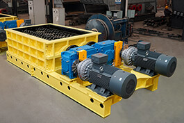
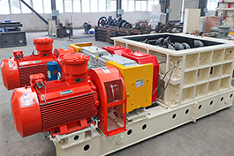
1.
Mineral sizers the main shaft of the motor and the input shaft of the working machine should be aligned with sufficient space between the motor and the working machine for the installation of the hydraulic coupler. The footing can be adjusted with gaskets or inclined blocks, etc. The different coaxiality errors and angle errors are required according to the following table: The main and slave joints are connected with a plico-shaped elastic block. Mm coupling type motor, machine axis line offset motor, machine axis tilt main, driven joint clearance yoxsj150 ~ ≤0.30 1/1000 3~5yoxsj500 ~ ≤0.35 0.5/1000 4~7yoxsj750 ~ ≤0.45 0.4/1000 6~9
The main and driven joints are connected by elastic sleeve unit: Mm coupling type motor, machine axis line offset motor, machine axis tilt main and driven joint clearance
Yoxsj150 ~ ≤0.05 0.3/1000 3~5
Yoxsj500 ~ ≤0.08 0.2/1000 4~6
Yoxsj750 ~ ≤0.12 0.2/1000 5~8
2. Install the
mineral sizers key on the shaft groove of the motor and the working machine respectively, and grease the shaft.
3. Smoothly load the coupling into the input shaft of the working machine. For the convenience of disassembly and assembly, the coupling with the input shaft of the working machine:
Flat key connection type: For length-diameter ratio greater than 1.5, choose gap fit, length-diameter ratio less than 1.5, greater than 1.3, choose transition fit, length-diameter ratio less than 1.3, choose interference fit. If the input end of the machine has a screw hole to prevent axial movement, to be fixed axially, it is necessary to use fastening bolts, stop rings, pins to fix the coupling with the machine, such as the input end of the machine without axial fixing requirements, this work does not need to be carried out.
4. Push the motor smoothly into the shaft hole of the active coupling of the coupling.
5. Tighten the anchor bolts of the motor and the working machine initially, and then check the motor shaft, and whether the different coaxiality and angle error of the input shaft of the working machine are consistent with the above table.
6. During installation, it is not allowed to tap
mineral sizers directly on the surface of the cast aluminum, nor is it allowed to install by heating
(2) disassembly sequence
1. First remove the anchor bolt of the motor, and then move the motor (together with the active coupling) away from the coupling.
2. Pull the coupler from the input shaft end of the motor. If it cannot be extracted due to long use time, it can be disassembled by extractor, or by using special disassembly bolts and nuts (whose threads are matched with the disassembly holes in the coupling shaft) against the input shaft of the motor to disassemble the coupling (the special disassembly bolts and nuts can be made by the user).


.jpg)
