In the process of using the
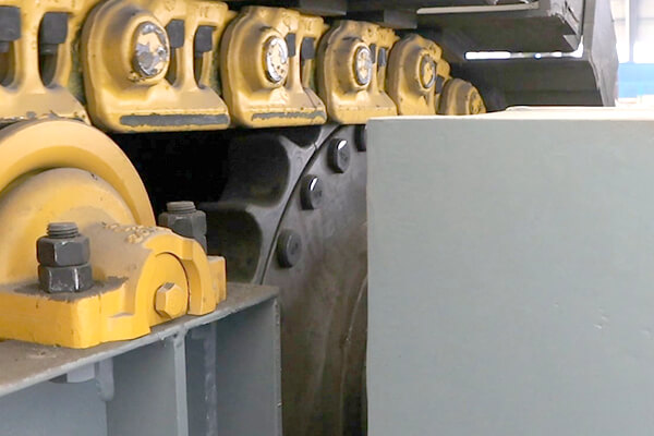
Apron feeder, due to the material weight and discharge impact, it is easy to cause the deformation of the plate feeder. In the existing plate feeder, the supporting wheel 3 is fixed on the frame through the supporting wheel shaft and the cover plate, and the frame is provided with a brace. Because the force is concentrated in the joint of the cover plate and the supporting wheel shaft, after long-term use, the supporting wheel shaft is prone to tilt, resulting in the sinking of the supporting wheel, making the supporting wheel fail.
Technical implementation elements:
Our company provides a plate feeder wheel support structure, simple structure, clever design, making the wheel support structure uniform force, stable and reliable, long service life.
Technical solution:
The
apron feeder supporting wheel supporting structure comprises a wheel supporting shaft and a wheel supporting, which is characterized in that a cylinder is provided, the cylinder is welded to the plate feeder frame, and the cylinder is arranged parallel to the plate feeder spindle; A supporting ring and a second supporting ring are arranged on the supporting wheel shaft. A supporting ring and a second supporting ring are arranged vertically with the supporting wheel shaft; A supporting wheel shaft is arranged in the cylinder, and the second supporting ring is located in the cylinder and matched with the inner wall of the cylinder; The two ends of the supporting wheel shaft extend out of the cylinder, and one end of the supporting wheel shaft is rotationally arranged with the supporting wheel, and the supporting wheel shaft is connected with the cylinder through the first supporting ring.
The inner wall of the cylinder end connected with the first support ring is provided with a ring groove; The first support ring comprises a first cylinder and a second cylinder, and the first cylinder and the second cylinder are coaxial arranged, and the outer diameter of the second cylinder is less than the outer diameter of the first cylinder; The second cylinder is inserted into the cylinder and matched with the ring groove. The first cylinder is connected with the cylinder flange.
The cylinder is located at the intersection of the frame riser and the frame riser. The cylinder is welded with the frame riser and the frame riser respectively. The cylinder outside the frame riser is supported by the frame riser.
Two symmetrical diagonal supports are arranged on both sides of the cylinder inside the frame riser. The diagonal support is arranged vertically with the frame riser, and the diagonal support is welded with the cylinder. The cylinder inside the frame vertical plate is supported by the frame vertical rib and the diagonal support.
The first support ring is near the support wheel. The first support ring and the second support ring are welded with the support wheel shaft.
Beneficial effects:
A) The structure adds a cylinder, so that the bearing point of the supporting wheel shaft is dispersed to the first support ring, the second support ring and its corresponding cylinder by the connection of a single cover plate and the supporting wheel shaft, and the first and two support rings are used to make the circumferential uniform force, so that the whole structure is more uniform, stable and reliable.
The utility model designs the first support ring as a step structure, which is convenient for the positioning of the first support ring, second to support the cylinder through the second cylinder part to disperse the force, and third to connect the first bead part with the cylinder flange to further improve the stability.
3) The utility model uses the vertical rib on the existing frame vertical plate to vertically support the cylinder, and on the side of the supporting wheel, that is, the position with greater force, two left and right oblique supports are added, and the cylinder is positioned through four supports to prevent the deformation and displacement of the cylinder and ensure the use effect of the supporting wheel. The wheel support structure of the utility model supports the wheel through the four directions of up and down and left and right, making it difficult to tilt and convenient to disassemble.
4) The position of the
apron feeder first support ring is designed to be close to the support wheel, and the side cylinder of the support wheel with greater force is strongly supported.
5) The first support ring and the second support ring are welded and connected with the support wheel shaft, which is easy to process and manufacture and has good stability.