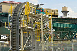
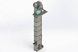
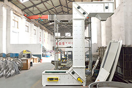
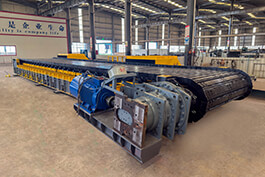
Bucket Elevator is widely used in industries such as metallurgy, chemical engineering, building materials, mining, grain and oil, plastics, medicine, food, and feed. Here is its basic structure.
Traction Components
The function of traction components is to bear and transmit power. They require high strength, good flexibility, low elongation, and light weight.
The commonly used ones are canvas belts and rubber belts. The canvas belt is made of cotton yarn and is mainly suitable for Bucket Elevators with small conveying capacity and lifting height, as well as dry working environment and materials. The rubber belt is made by vulcanizing several layers of canvas belts and rubber together and is suitable for Bucket Elevators with large conveying capacity and lifting height.
The joint of the elevator belt is incorrect, meaning the edges of the elevator belt are not on the same straight line. During operation, one side of the elevator belt is tight while the other is loose, causing the elevator belt to move towards the tight side and resulting in deviation.
The inner surface of the elevator belt and the head pulley are too smooth, causing the elevator belt to slip. A layer of glue can be applied to the inner surface of the elevator belt to prevent it from slipping.
The belt joints are generally connected by either overlapping or clamping methods:
Overlapping: When overlapping, it is necessary to ensure that the inner joint of the overlap is along the movement direction of the Bucket Elevator. Otherwise, the operation of the unit will be unstable and deviation will occur.
Clamping: When using clamping, a special fixture should be used. The fixture should evenly clamp the belt, the holes should be accurately made, and it should be tightened with a special tightening bolt.
Buckets
Buckets are the components used to hold and transport materials. Depending on the material, there are metal buckets and plastic buckets:
Metal Buckets: Buckets are made by welding, riveting or stamping 1-2mm thick ordinary carbon steel or galvanized steel. If the material is of poor quality, the strength is limited and the bucket is prone to falling off.
Plastic Buckets: They are made of polypropylene plastic. They have the advantages of being lightweight, low in cost, wear-resistant, and not generating sparks when colliding with the barrel.
Buckets are fixed with specific U-shaped bolts. Common Buckets are classified by shape as Q-type (shallow bucket), H-type (arc-bottom bucket), ZD-type (medium-deep bucket), and SD-type (deep bucket).
The larger the bucket opening and the smaller the belly, the easier it is to fill. Therefore, Buckets are often in the shape of a triangle with a large opening and a small belly; the faster the running speed, the more backfilling there will be; if the spacing between Buckets is too small, it will be found that some materials are thrown out and hit the bottom of the previous bucket and then bounced back.
The head wheel and the bottom wheel
The head wheel and the bottom wheel are also respectively called the driving wheel and the driven wheel. The driven wheel also plays a role in tensioning. They are installed on the machine head and the machine base, and they are the supporting components of the elevator belt.
A reverse stopper is set on the head wheel to prevent the traction component from reversing; a speed difference monitor is installed on the bottom wheel shaft to prevent the traction component from slipping.
If the bearings of the head wheel and the bottom wheel do not rotate smoothly, the resistance torque increases, causing the elevator belt to slip; the slower the rotation speed of the head wheel, the greater the degree of the hopper being filled.
The head wheel shaft and the bottom wheel shaft should be parallel to each other and in the same vertical plane, and the allowable deviation of their parallelism is 0.6mm/m.
Base Unit
Comprising base casing, bottom pulley, shaft, bearings, take-up device, feed inlet, etc.
Loading refers to the process in which buckets scoop materials while passing through the lower half of the base unit.
Based on different feeding directions, loading modes are categorized as concurrent feeding and counter feeding. Counter feeding is widely adopted in engineering applications, where the feeding direction aligns with the bucket travelling direction for a high filling factor.
Two types of take-up devices are available for the base unit: spring take-up and weight-box take-up.
During operation, if lumpy materials or foreign objects get jammed inside the base unit, shut down the equipment to clear the blockages. Install wire mesh screens at the feed inlet to prevent foreign debris from falling into the base unit.
Prior to base installation, thoroughly prepare the base foundation. The foundation is fastened with anchor bolts. The elevation of the foundation surface shall range from -20 mm to 0 mm, with a centerline tolerance of ±10 mm. The flatness and roughness of the surface shall also meet specified requirements.
Shims are used to adjust the horizontal level of the base, with a spirit level for measurement. The longitudinal and transverse flatness tolerance is 1 mm per meter. Feeler gauges shall be used to inspect the contact ratio between the base and foundation, which shall be no less than 75%.
The elevator leg is assembled from multiple sections according to different lifting heights, normally of rectangular configuration. Each section is fabricated from thin steel plate with a length of 1–2 meters, and adjacent sections are bolted together via angle iron flanges.
A elevator belt deviation alarm device is installed inside the elevator leg to send timely alarms once the traction component drifts off track.
The intermediate casing is divided into inspection sections (fitted with access doors), deviation adjustment sections (for belt widths over 650 mm) and standard intermediate sections.
Classification of intermediate sections: primary intermediate section, standard intermediate section, intermediate section with inspection hatch, non-standard intermediate section.
Sealing between casing segments is achieved with 2 mm-thick rubber gaskets, waterproof canvas, asbestos gaskets and asbestos rope; sealant can also be adopted as an alternative sealing solution.
Observation windows shall be arranged at appropriate positions where the elevator leg passes through each floor. Partial intermediate sections are equipped with access doors for maintenance purposes.
After full assembly of the bucket elevator, section steel such as angle steel or channel steel shall be applied for lateral and longitudinal positioning to eliminate equipment swaying. Permanent welding or rigid clamping is prohibited, as the vertical casings will experience thermal expansion and contraction.
Drive device
The drive device is divided into left-mounted and right-mounted (facing the feeding port).
There are two types of reducers: YZ type shaft-mounted reducer and ZQ type reducer.
There are three ways to connect the drive device with the head pulley: coupling, pulley and sprocket.
Bucket Elevator couplings have two types: cross slider coupling and elastic pin coupling.
The speed regulation methods of Bucket Elevator include rotor series resistance speed regulation and using frequency converter speed regulation.
To ensure constant voltage and current, and to avoid unstable voltage or excessive current that may burn the motor, auxiliary equipment such as an electrical control box can be added.
Most Bucket Elevators with heavy loads are equipped with hydraulic couplings. The hydraulic couplings enable the Bucket Elevator to have an automatic protection function. Once due to blockage or other reasons, the entire machine is overloaded, the hydraulic couplings will burst to automatically protect, and the oil and quality of the couplings must meet the technical requirements.