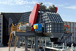
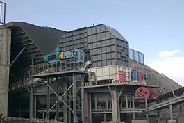
Apron Feeders are widely used in the processes of mining, selection, transportation, batching, etc. in mining, cement, chemical and metallurgical enterprises. Apron Feeder is suitable for large and medium-sized cement plant production lines. It can be used to deliver various blocky or loose materials from storage bins to crushers, conveyors or other working machinery in a horizontal or inclined direction. There are light, medium and heavy types. It is widely used in industries such as mining, metallurgy and cement, and is an indispensable equipment in raw material processing or continuous production processes. It is particularly suitable for handling large and sharp materials. The heavy-duty Apron Feeder, as an important component of the crushing station for mining equipment in the mine, is responsible for uniformly and continuously conveying various bulk density materials from excavators to the crushing stage, playing a crucial role in the semi-continuous mining process.
Working principle
The heavy-duty Apron Feeder uses the power from the motor to drive the sprocket shaft to rotate through a coupling and a reducer. The sprocket teeth fixed on the sprocket shaft then continuously mesh with the chain, driving the chain plate to move continuously in a straight line, and continuously transporting the materials to the crusher, thus achieving the purpose of conveying materials.
Structural characteristics
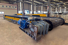
The main components of the Apron Feeder include: main frame, drive shaft assembly, tensioning device, standard traction parts (chains, idler wheels, drag sprockets, etc.), chain plates, and drive unit.
Mainframe frame
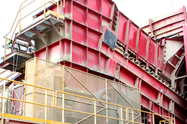
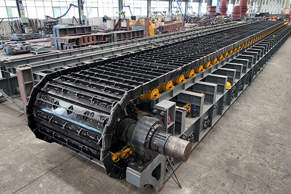
The mainframe frame is the main steel structure of the Apron Feeder, providing rigid support for all mechanical components and being capable of withstanding all loads during the start-up, operation and incoming material impact of the equipment. The head of the main frame is equipped with a drive shaft, which is supported by a bearing housing installed on the frame. There is a tensioning device at the tail. The entire device is fixed in the slot holes of the frame and the entire chain is tensioned through a hydraulic jack. The working section of the chain is supported by the idler wheels installed on the frame. The empty return section of the chain is supported by the drag sprocket installed on the frame. Therefore, when the self-weight of the chain plates and the impact of incoming materials occur, almost all the loads are borne by the main frame, and it is necessary to ensure the strength and rigidity of the main frame.
The main frame adopts a four-layer structure. The topmost layer is the installation layer for the idler wheels and rails. It is necessary to ensure sufficient flatness to avoid inconsistent heights of the left and right chains, which may affect the transmission efficiency. The second layer is the reinforcement plate support layer. The third layer is the empty return layer of the chain, which is used to install the drag sprocket and minimize the sag of the empty return section of the chain. The fourth layer is the installation surface layer of the entire Apron Feeder.
Drive shaft assembly
The drive shaft assembly includes the drive shaft, sprocket, expansion sleeve, rolling bearing and bearing housing, etc. The two bearing housings on the left and right are installed on the Apron Feeder frame, and the rolling bearings inside support the drive shaft. The sprocket adopts a split structure, and a single sprocket is fixed to a machined steel hub by bolts. This wheel is installed on the drive shaft and is equipped with a locking device.
The drive shaft serves as the link between the drive device and the chain plate. The drive shaft not only bears the torque of the reducer but also its mass. Therefore, the size of the drive shaft should be checked according to the final force condition. Select the appropriate bearing and calculate the bearing life based on its equivalent dynamic load to determine whether it meets the working conditions and service life requirements.
Tensioning device
The tensioning device consists of a fully welded box structure, which is used to support two tensioning wheels. The tensioning device is fixed to the main frame by bolts and can slide in the slot holes of the frame. The tensioning of the chain can be simply achieved through a hydraulic jack and the insertion and removal of gaskets. The hydraulic jack is controlled by an on-board manual hydraulic pump, which can achieve timely adjustment of the tension force. There is an installation position for the tensioning device left on the main frame. One end of the jack is fixed on the frame, while the other end can be extended and retracted to achieve the tensioning of the tensioning wheel and the chain. The tension force of the chain is composed of circumferential force, the self-weight of the chain, initial tension and the additional dynamic tension force generated by the multi-sided effect during the operation of the chain. It is an important basis for the design of the drive shaft.
Standard traction component
The Apron Feeder adopts a double-chain structure. On both sides of the Apron Feeder mainframe frame, there are support wheels installed under the chain. The idler wheel is mainly used to support the working section of the chain, preventing the chain plate from experiencing significant deflection due to load and self-weight, ensuring the normal operation of the chain and withstanding the impact of some materials, and can also limit the deviation of the chain. The design spacing of the idler wheels is sufficient to support the chain and the chain plate assembly. Inside the main frame, the return section of the chain is equipped with a drag sprocket to prevent excessive deflection of the return chain, which could affect the transportation efficiency of the chain.
Chain plate
The chain plate of the Apron Feeder is fixed to the chain track by high-strength bolts and nuts. The middle part of the main frame is equipped with a buffer rail, and the middle part of the chain plate is located above the buffer rail. It is an integral welded structure and is provided with reinforcing ribs and support plates. The chain plate of the Apron Feeder adopts a leak-proof overlapping design to minimize material jamming on the chain plate. Moreover, the side of the chain plate is equipped with a high-edge skirt plate to prevent material spillage.
The chain plate can be replaced at the work site without affecting other parts of the equipment. The chain plate is supported by the idler wheels and supporting wheels installed on the frame, and the chain and sprocket mesh correctly by adjusting the tensioning device. The middle part of the mainframe frame is equipped with buffer rails, which can minimize the deformation of the Apron Feeder chain plate and provide sufficient support for the entire carrying section of the Apron Feeder. Because the Apron Feeder has a certain usage Angle when in use, scrapers are welded on the chain plates to facilitate the transportation of materials. To prevent material sticking to the chain plates and material leakage in the empty return section of the chain, the Apron Feeder is also designed with a material receiving device and uses the scraper in the empty return section of the chain to scrape the accumulated leaked material to the ground.
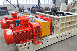
Drive unit
The drive unit is composed of an electric motor, a coupling and a reducer, etc. The electric motor provides the original power, the coupling ensures the smooth transmission of power, and the reducer reduces the high-speed rotation of the electric motor to a low speed suitable for the rotation of the sprocket shaft, so as to meet the requirements of material transportation.
Providing power is the main function of the motor. The conveying speed of the plate feeder can be adjusted by controlling the operation of the motor to meet different production requirements and material characteristics. And the motor is equipped with overload protection devices to prevent motor damage and ensure the safe operation of the equipment.
The main function of the reducer is to convert the high-speed rotation of the motor into a lower-speed rotation, to meet the operational requirements of the apron feeder and achieve stable material transportation.