Introduction
Compared with belt conveyors, scraper conveyors, etc., the Apron Feeder has a stronger adaptability to materials and can handle large-sized, high-density, highly abrasive and certain-temperature bulk materials. It plays an irreplaceable role in the mining and heavy industry sectors. In the structural components of the Apron Feeder, the head shaft and tail shaft, as the core rotating parts of the entire chain plate operation system, their design rationality and manufacturing accuracy directly affect whether the entire machine can operate stably for a long time.
Structural differences and functions of the head shaft and tail shaft of the Apron Feeder
Head shaft
The head shaft is the driving shaft of the Apron Feeder, which transmits the torque output by the driving device to the sprocket, and then drives the chain and chain plate to operate. Drive sprockets are installed at both ends, and the sprockets are fixed to the shaft through key connections, expansion sleeve connections, or other methods. Bearing seats are installed on both sides of the frame, and the driving device is connected to one end or the middle of the head shaft through a coupling or other transmission methods to input power to the shaft system.
Function
Drive torque, which is the torque output by the reducer and transmitted to the sprocket;
Chain tension, including tight side tension and loose side tension, the tension of both sides of the chain acts on the shaft and generates bending moment;
Material load, which is the weight of the materials on the chain plate and is transmitted to the shaft through the chain and the sprocket;
Additional dynamic load generated by the meshing of the sprocket, including periodic impacts caused by the polygon effect;
Inertial loads during startup and braking processes.
Tail shaft
The tail shaft is the driven shaft of the Apron Feeder, supporting the tail sprocket or guiding components, guiding the chain and chain plate to complete the rotary motion, and bearing the chain tension and the radial load generated by the sprocket. Compared with the head shaft, the load borne by the tail shaft is mainly bending load, and the torque is usually very small or zero (except in special cases).
Function
Withstanding the radial load caused by the chain tension and transmitting it to the frame to ensure the stability of the shaft system
Assisting the chain tensioning device in providing support and cooperating with the tensioning device to adjust the tightness of the chain;
Withstanding the load transferred by the chain plate and the weight of the materials through the chain and the chain wheel, ensuring smooth rotation movement;
Limiting the lateral movement of the chain to ensure the stability of the chain plate running path and avoiding deviation faults.
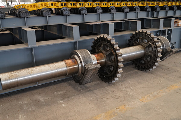
Key factors in the design of the Apron Feeder shaft system
Shaft diameter and bearing capacity
The shaft diameter is the diameter of the steel shaft. The larger the shaft diameter, the more likely it can withstand bending and torsional loads, but the exact thickness needs to be determined based on the actual force calculation.
Bearing capacity refers to the load that the shaft can withstand without unacceptable bending, torsion, fatigue damage, etc. It is not only determined by the shaft diameter, but also by the material, length, support position and force size of the shaft.
During actual design, the determination of the shaft diameter requires first calculating the force the shaft can bear, the tension of the chain, the driving torque, and then calculating the shaft diameter based on the load, bearings span and materials, checking for bending or twisting damage, and finally checking the bearings and connection parts.
Requirements for shaft processing
The shaft processing of Apron Feeder includes forging, annealing, rough machining, shaft flaw detection, and fine machining. Under the premise of reasonable material, heat treatment and structural design, the forged shaft is conducive to meeting the strength and toughness requirements of Apron Feeder in heavy-load conditions.
Forging: The forging process requires strict control of the forging ratio to ensure that the internal porosity, gas holes and other defects in the steel ingot are compacted. Annealing treatment is used to eliminate the internal stress generated during forging and improve the cutting processing performance of the steel.
Flaw detection: After rough machining, the shaft blank needs to be magnetically or ultrasonically inspected first to check for hidden cracks, slag inclusions and other defects.
Fine machining: The dimensional tolerances, shape tolerances and surface roughness of each shaft section need to be strictly controlled, with a focus on ensuring the coaxiality of the shaft sections for installing bearings and chain wheels.
Non-destructive testing methods for the Apron Feeder shaft
Magnetic Particle Testing (MT)
The Apron Feeder shaft is usually made of carbon steel or alloy steel and is a ferromagnetic material, fully meeting the applicable conditions for magnetic particle testing. Through magnetic particle testing, tiny cracks, hairlines, and other defects on the surface and near the surface of the shaft blank can be precisely detected.
Ultrasonic Testing (UT)
Using high-frequency sound waves to propagate through the material, when encountering internal defects (such as internal cracks, inclusions, folds) or interfaces, they will produce reflections. By receiving and analyzing the reflected waves, the location and size of the defects can be determined.
For longer shafts, longitudinal waves or transverse waves are often used for testing, and phased array technology can also be combined to improve detection accuracy and coverage.
Penetrant Testing (PT)
Penetrant testing is suitable for detecting tiny cracks, hairlines, etc. on the surface of the Apron Feeder shaft that may be difficult to identify or not applicable to magnetic particle testing. Especially for defects with low surface roughness and clear openings, penetrant testing has higher sensitivity.
Conclusion
The head shaft and tail shaft of the Apron Feeder have different functional positions, corresponding to different load characteristics and design requirements. During the manufacturing process, strict process control measures must be followed. Through standardized forging treatment, quality inspection, and precision processing, the shaft system can ensure that it meets the strength, toughness, and precision requirements under heavy-load conditions, providing reliable support for the long-term stable operation of the Apron Feeder complete machine.


.jpg)