In modern industries such as chemical engineering, pharmaceuticals, food processing, mining, and lithium battery new materials, dust-free, efficient, and low-loss transportation of powder and granular materials is a crucial aspect for ensuring continuous production. The Tubular Drag Conveyor, with its significant advantages such as flexible three-dimensional layout, fully enclosed dust-free environmental protection, low energy consumption, and low material damage rate, is rapidly replacing traditional bucket elevators, spiral conveyors, and pneumatic conveying systems.
However, in actual engineering bidding and equipment procurement, many enterprises encounter frequent equipment failures such as chain breakage, blockage, abnormal wear of discs, pipeline leakage, or motor overload after equipment commissioning due to mismatched selection parameters and insufficient assessment of working conditions, resulting in production losses.
This article will conduct a systematic technical dissection and parameter comparison from seven dimensions: material characteristics, conveying capacity, topological layout, material environment, and special working conditions.
Material characteristic assessment
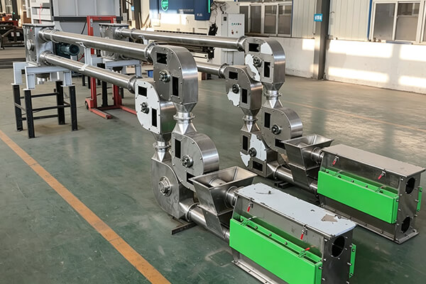
The Tubular Drag Conveyor is a physical mechanical scraper-type conveying equipment. The material moves forward in the closed pipeline under the thrust of the chain and discs. The physical and chemical properties of the material directly determine the pipe diameter, chain tension level, disc material, and motor power of the equipment.
Bulk Density and Particle Size Distribution
Bulk Density (t/m³) The bulk density of the material is a core parameter for calculating motor shaft power and chain tension. The greater the density, the more the chain resistance increases, and a chain with greater tensile strength (such as forged chain or heavy-duty plate chain) and a high reduction ratio drive unit need to be selected.
Particle Size Distribution (mm): The size of the particles determines the lower limit of the pipe diameter (DN). Generally, the inner diameter of the Tubular Drag Conveyor pipe must be 3 to 5 times larger than the maximum particle size of the material; for materials that are prone to entanglement and have poor fluidity, the pipe diameter ratio needs to be further increased to completely eliminate blockage and bridging phenomena.
Moisture & Flowability
Good fluidity (angle of repose < 30°): The filling rate of the material can be appropriately increased (up to 60%–70%), and the conveying efficiency is high.
High moisture content / viscous materials (angle of repose > 45° or prone to agglomeration): They tend to accumulate and adhere at pipe elbows or disc groove areas. For such conditions, anti-adhesion discs (such as PTFE coating or high molecular ultra-high polyethylene) must be selected, and a scraper, vibration flow aid device or pneumatic impact device should be configured at the discharge port.
Machinability and Corrosion Resistance
Strongly machinable materials: Thickened wear-resistant alloy steel pipes / inner wear-resistant ceramic pipes must be used. Chains must undergo hardening heat treatment such as carburizing and quenching, and disc plates must be made of wear-resistant synthetic materials.
Strongly corrosive materials: The flow components in contact with the materials need to be upgraded to SS304, SS316L, duplex stainless steel (2205) or titanium.
Transportation capacity and layout
Calculation of transportation capacity
The theoretical volumetric transportation capacity calculation formula for Tubular Drag Conveyor is:
Q = 3600 × A × v × η
Q: Volumetric transportation capacity (m²/h)
A: Pipe cross-sectional area (m²)
v: Chain linear speed (m/s, usually controlled within 0.1 - 0.4 m/s to reduce wear)
η: Volume filling rate (depending on the fluidity of the material, usually taken as 30% - 70%)
Selection suggestions: For high-wear and fragile materials, a selection strategy of "large pipe diameter, low linear speed, and low filling rate" should be adopted to extend the equipment's service life; for materials with good fluidity and light weight, the linear speed and filling rate can be appropriately increased to reduce equipment investment costs.
Layout
The main advantage of Tubular Drag Conveyor lies in its ability to perform "horizontal-vertical-horizontal" three-dimensional continuous conveying, reducing transfer links and dust collection points. However, when designing the layout, the resistance must be strictly calculated:
Horizontal distance and vertical height: The power required for vertical lifting and the chain tension are much greater than those for horizontal conveying. The maximum conveying distance of a single Tubular Drag Conveyor is determined by the breaking strength of the chain (typically the horizontal distance can reach up to 60 meters, and the vertical distance can reach up to 30 meters).
Number and angle of elbows (30°/45°/90°): The centrifugal force and turning friction of the material at the elbow are the main sources of system resistance. For each additional 90° elbow, the operating resistance is equivalent to an increase of 3 to 5 meters of horizontal straight pipe. Therefore, when designing the layout, the number of elbows should be minimized as much as possible, and large-radius elbows with a radius of 1000mm should be preferred.
Planning of inlet and outlet
Multiple-point feeding: A quantitative feeding device (such as a lockable star-shaped discharge valve or a screw feeder) should be installed below the feeding port to prevent the material from instantly filling the pipeline, causing "stuck and blockage".
Multiple-point discharging: Use pneumatic/manual air tight plug valves, combined with a pipeline with no dead corners transition design, to ensure smooth discharging and no residual materials.
Comparison of key parameter differences and selection of Tubular Drag Conveyor
Tubular Drag Conveyor Configuration Parameter Comparison Table
|
Parameter/ConfigurationDimension
|
Standard/BasicConfiguration
|
Mid-range/Wear-resistantConfiguration
|
High-end/SpecificOperatingConditionConfiguration
|
SelectionImpactandEngineeringSignificance
|
|
PipeNominalDiameter
(DN)
|
DN80 / DN100
|
DN150 / DN200
|
DN250 / DN300+
|
Determines the upper limit of the conveying volume and the maximum allowable material particle size
|
|
ChainStructureType
|
Industrial Standard Ring Chain (Ring Chain)
|
Hardened Alloy Steel Ring Chain / Pin Shaft Plate Chain
|
Forging Heavy-duty Chain / Corrosion-Resistant Duplex Steel Chain
|
Decides the maximum conveying distance, tensile strength, and elongation
|
|
DiscMaterial
|
Ordinary UHMW-PE / PU
|
Moisture-Resistant Modified Polymer / PTFE
|
PEEK / 304/316L Metal Discs
|
Defines the upper temperature limit (limited < 200℃), wear resistance, and food-grade compliance
|
|
ChainLinearSpeed
(unit:m/s)
|
0.3~0.4
|
0.2~0.3
|
0.1~0.2(low speed)
|
The lower the speed, the more significantly the material damage rate and pipeline wear will be reduced.
|
|
Designfillingrate
|
50.0%~70.0%
|
40.0%~50.0%
|
30.0%~40.0%(Underfilling)
|
A low filling rate can effectively prevent material clogging and overloading of the pile.
|
Summary
The Tubular Drag Conveyor model selection process does not merely involve choosing the "maximum conveying capacity" or the "lowest price", but rather achieves a perfect match among the material characteristics, the topological space, the operational lifespan and the safety regulations.


.jpg)